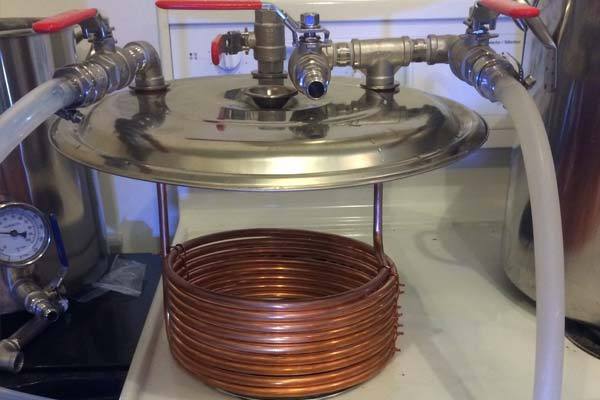
Many homebrewers desire a brew system that does it all. We want more control over temperature, efficiency and the consistency of our brews. One solution is a HERMS system (Heat Exchange Recirculating Mash System) – an advanced set up that requires some level of automation.
A HERMS system relies on heat exchange where either a copper coil is immersed in the hot liquor tank (HLT) or another external vessel that is filled with hot water. The mash water is then pumped through the coil, picking up heat from the surrounding water, and returned to the mash lauter tun (MLT).
Chad Takahashi shared how to build a HERMS lid with us below!
Inspiration
I decided to go with a HERMS system for a few reasons. I like the idea of an all electrical brewery set up. Brew days are easier and 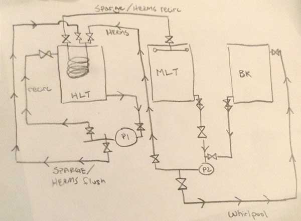 simpler. I also wanted more control over my mash temperature to better control which enzymes are working on my beer. Consistency was another issue. If I ever want to repeat a recipe, the HERMS system gives me the recipe consistency that I otherwise didn’t have on my previous set up.
Although it’s not complete, I still have the benefits of mash recirculation and temperature consistency for the entire mash. I decided to use the lid of my pot because the pot itself is a light economy style pot that has thin walls and I wasn’t sure if it could handle the weight of a coil and a couple valves. The weight could make it front heavy and cause the pot to tip over when it’s empty.
HERMS Lid Materials & Construction
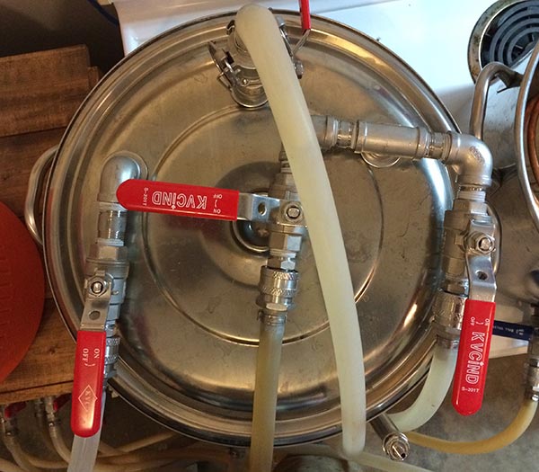 Looking at the photo of the lid, the valve is for recirculation of the HLT to prevent heat stratification of the water inside the HLT. The valve on the left is the out from the HERMS coil to the sparge arm in the mash tun. The center valve is the input from the mash tun to the HERMS coil and the right hand valve is the input from the HLT. I flush out the coil with the sparge water and fly sparge.
I built a 25′ wort chiller of 3/8″ copper around one of my corny kegs and used a tubing bender to bend the copper so that it’d fit the lid. I used 14 gauge copper wire and tied the coil to hold everything together.
I drilled 2 7/8″ holes with a step bit into the top of the lid so that my compression fittings would line up with the copper tubing. I installed the valves into the lid and then the copper coil into the compression fittings.
- 25′ of 3/8″ copper tubing
- 4 1/2″ 304 SS ball valves
- 2 1/2″ MIP x 3/8″ compression fittings
- 3 1/2″ x 2″ SS nipples
- 3 1/2″ SS 90 degree elbows
- 1 1/2″ SS Tee
- 1 1/2″ X close SS nipple
- 1 1/2″ MPT SS lock nut
- 4 1/2″ male MPT quick disconnects
How it Works
My brewery consists of two 8-gallon kettles (HLT and brew kettle), and a 10 gallon Igloo mash tun with a false bottom. I have two 12 volt pumps with magnetic drive impellers, one for water and the other for wort.
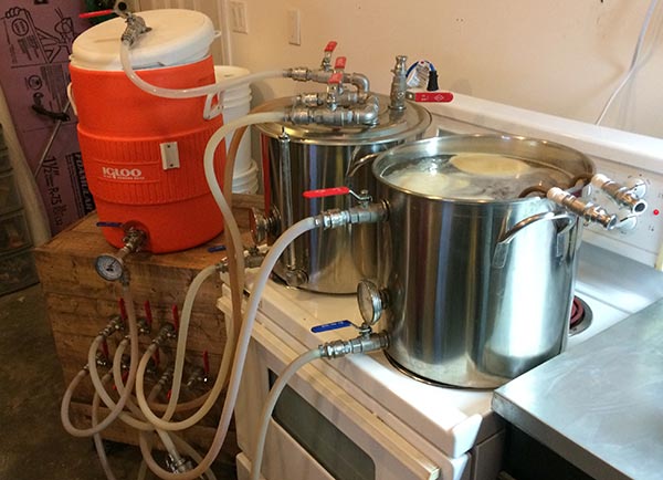 I start my brew day by filling my mash tun with the required water volume and the HLT with my sparge volume. I turn on the heat to the HLT and heat up my mash water by cycling it through the HERMS coil that’s built into the lid. Once I reach my strike temperature, I’ll dough in and turn down the temperature on the HLT to maintain my mash temp while continually cycling the mash to get a nice clear wort to transfer to the brew kettle.


Share Post